
Ficep LEXINGTON Automatic CNC 4-Sides Scribing Lines for Sections
4-sides sections scribing
Automatic CNC 4-sides scribing lines for sections. The Lexington CNC layout system for structural steel members addresses the most labor-intensive process in structural steel fabrication. The need for a layout man to interpret a drawing, using a measuring tape and square to manually mark locations for detail members to be fit on the main member is eliminated.

Types of Processes
- Scribing
Section Shapes
Beams

Angles
Flats

Channels

Square tubes

Rectangular tubes

Main Features
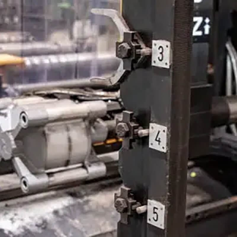
Independent Scribing Heads

The Lexington features four totally independent marking heads each with their own sub-axis travel of 350 mm (13-3/4”) on both the vertical and horizontal heads so it is possible to mark up to four surfaces simultaneously even when the marking requirements are offset between the surfaces.
Automatic Tool Changer
An automatic tool changer for the vertical and horizontal heads, each with 6 positions, is furnished to be able to select for the layout to be generated with milling, scratching, pencil or pointing.
Patented Scribing Tool
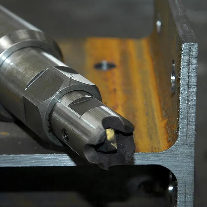
Each of the four marking heads are equipped with Ficep patented scribing tools, using a 4-sided carbide insert that generates a high speed milling function to mark or scribe the surfaces. The tool is designed to float to maintain a consistent depth of penetration for marking. The mark penetration of the tool is designed to also be adjustable so that deeper penetrations could be achieved for part marking of material that was subsequently galvanized or painted.
Automatic CAD Data Import
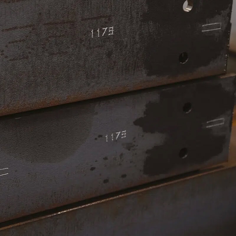
FICEP’s industry leading software is able to extract all the intersecting locations of the different structural steel elements from the 3-D model of the structure. In addition to these locations, an orientation mark, the part number of the element to be fit and the welding codes are also generated on all four surfaces by the Lexington.
Advantages
- Eliminate the need for a layout man to manually generate layout marks and locations.
- Download all the layout locations, orientation of the mating members, generate and mark the welding code information and indicate the part number of the intersection element automatically. No manual programming is required.
- Perform layout on up to 4 surfaces simultaneously with sub-axis positioning on each spindle.
- Select layout using milling, scratching, pencil or pointing with the systems automatic tool changer.
Technical Specifications
| LEXINGTON | Section size [min. mm] | Section size [max. mm] | Scribing heads [no.] | Scribing tools per head [no.] | Spindle speed [max. RPM] | Spindle sub-axis stroke [mm] | Machine weight [kg] |
|---|---|---|---|---|---|---|---|
| 1203 VLS | 80 x 10 | 1220 x 610 | 4 | 6 | 5000 | 350 | 11500 |
Montfort International
G1P 3T3, Canada